

Posts Tagged ‘closed cooling’
Mercruiser Closed Cooling System Flow Diagram
Monday, February 10th, 2014 |
 |
 |
CHECK INVENTORY & SHOP ONLINE: Click Here
Question: Do the Mercruiser Engines equipped with the Dry Joint Style Exhaust AND Closed Cooling systems circulate antifreeze through the exhaust manifolds?
Answer: Mercruiser has made changes over the years between 1/2 and FULL cooling systems. The driving factor for this was the same reason that always seems to govern manufacturers and their products; cost. Up until 1992 Mercruiser had almost always configured their marine cooling systems, both raw water and fresh water cooling systems, such that they included warm manifolds. However in 1992 when Mercruiser introduced the 502 mag EFI motor the intake plenum was so large that it interfered with the standard thermostat housing and therefore prevented them . Therefore Mercruiser set out to determine if there were functional issues to back up the concerns that the exhaust manifolds could not be allowed to run colder than engine temperature. Mercruiser performed a significant amount of functional testing with the cold manifold systems and the resulting effect of condensation. They determined through this testing that no functional damage resulted that could be attributed to the cold manifolds. Therefore starting in 1992 with the introduction of teh 502 Mag MPI Mercruiser offered the first of several engines with the cold manifold style cooling system.
However around the 2000 model year Mercruiser realized that the cost of warranty related to condensation induced engine damage had escalated significantly over the past 8 years and was becoming a real issue. Therefore when the 8.1L engine was released in 2001 it was determined that there was no achievable way to introduce this new engine with a warm manifold type cooling system. Therefore several specific system designs were implemented on this engine to allow it to also be released with the cold manifold type cooling system. However in 2002 the decision was made that going forward all new designs would be done while including a warm manifold cooling system unless this was just not possible.
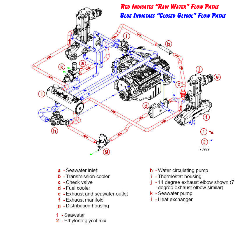
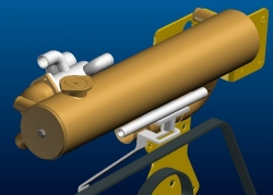
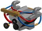
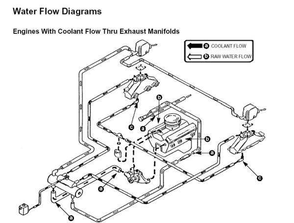
Cooling Flow Diagram: Therefore referencing the above flow diagram we want to point out a few of the following Mercruiser specific features:
- Reference Item “C” Check Valve – This is a patented feature offered by Mercruiser. Since Mercruiser offers the easy to use Single Point Drain system’s they have to take into account that preventative features are required to prevent water entering the boat when the draining is underway. Historically this was done manually when draining was performed with the boat remaining in the water by using a manually operated ball valve.
- Reference Item “G” Distribution Housing – This patented feature is specific to Mercruiser and required to support the single point drain feature. All of the incoming water is tied into a centrally located housing which can then be used as a location for draining. Note that a derivative of this housing is used with the raw water or open cooling systems.
- Reference Item “I” Thermostat Housing – Mercruiser utilized a full flow thermostat housing that direct flow through the heat exchanger or through the bypass circuit at all times. This is a key feature of Mercruiser Cooling System in that regardless of the thermostat position, the engine always experiences 100% coolant flow. This is important to engine operating efficiency because it’s not always the coolant temperature rather the coolant flow that determines if and when detonation occurs. Therefore an engine with maximum flowrate through the cylinder heads offers the best opportunity for achieving the maximum spark timing.
High Capacity versus Standard Capacity Marine Fresh Water Cooling Systems
Wednesday, February 15th, 2012
The main area of difference with a Premium System is that coolant is forced thru the exhaust manifolds before it passes through the heat exchanger thus it is referred to as a full flow system. With these type systems flow is maintained throughout the exhaust manifolds and engine block at all times and therefore potential “Hot Spots” are minimized. These systems utilize a dual acting type thermostat which regulates an internal bypass system such that even when the thermostat is in the closed position full flow is maintained through the engine.
Standard Systems
These system have bypass functionality integrated into the thermostat to allow a small amount of flow thru the thermostat in the closed position. Thus when the engine is cold the only flow thru the engine is what bypasses thru the thermostat bypass. This also prevents the exhaust manifolds from over-heating during engine warm up.
High Capacity
This term is used to describe particular design features such as 6 raw water passes, a tighter tube pitch meaning a higher number of cooling tubes, sealed dividers which means leakage between the passages is minimized. All of these features require a higher level of material and labor and therefore typically indicate a higher cost. This also typically indicates a heavier unit due to having more internal cooling material. Although overall system capacity is ultimately determined by the capacity of the raw water pump supply the efficiency of the heat exchanger allows the high capacity systems to compensate for the lower flowing pumps and therefore provide a higher overall system margin.
Marine Cooling Systems Technical Tips Newsletter
Wednesday, February 15th, 2012|
Welcome to the Monthly Technical Tips Newsletter. In conjunction with our goal aimed at serving the retail customer, the purpose of this newsletter is to further assist customers in understanding the basics of the marine products they purchase and own. Your feedback is greatly appreciated and helps us to continue providing you with helpful information. Please feel free to respond back to us and let us know if this type of information is valuable to you, as well as suggesting future topics you would like to see included [email protected].
“MARINE COOLING SYSTEMS”
Fresh Water Cooling
Fresh Water Cooling vs. Raw Water Cooling, Open Cooling vs. Closed Cooling, 1/2 vs. Full Systems . This months technical tips letter is aimed at addressing many of the common questions and misunderstandings relating to the different types of Marine Cooling Systems. This time of year after going through the pains of draining the engine in preparation for cold weather , many are ready to investigate the various benefits of the closed type of cooling system. Relating to the Marine industry Closed Cooling refers to a cooling system that utilizes a closed/pressurized system containing a standard antifreeze type mixture within the engine block and/or exhaust manifolds. These types of systems utilize some type of a a heat exchanger to remove the heat from the antifreeze. Most common are the standard tube in shell type heat exchanger….. Read More About Fresh Water Cooling Heat Exchangers
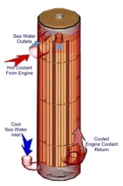
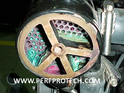
Engine cooler units are very similar to oil & power steering coolers and vary in size most commonly between 4″ & 5″. The terminology “# of passes” refers to the dividers in the raw water portion of the cooler and usually range between 3 & 6 in number. When looking at these “passes” when removing the end cap of the cooler and looking into the end they will appear as dividers similar to a pie being cut into pieces. This effect of this is that the water flow velocity is increased and therefore coolant efficiency is benefited. One common misconception is that increasing the coolant flow rate and velocity therefore does not allow the coolant time to properly remove the heat from the system. Marine Water Pumps
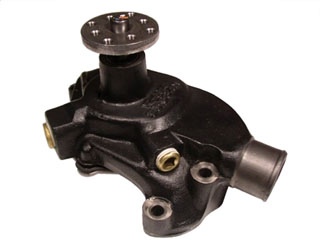
Regarding marine water pumps there are two different pumps of most concern; circulating pumps & raw water pumps . The circulating pump is very much like the pump on an automotive engine except with a bronze impeller, ceramic face seals and stainless steel backing plate. These pumps are typically bi-directional and fall into the category of “centrifugal pumps”.
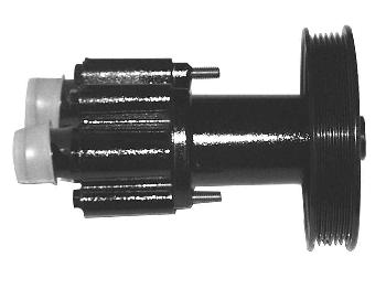
The other pump family is a positive displacement pump meaning it actually produces lift capacity and can be thought of as the pump that supplies the raw water to the circulating pump in an open cooling system. In a closed cooling system this actually pumps the raw water through the raw water (tube) side of the heat exchanger. This raw water is then removing the heat from the anti freeze that the circulating pump is circulating through the engines and/or manifolds. Raw water pumps are typically belt driven, crankshaft driven, or in Mercruiser case with the Alpha sterndrive mounted inside the lower unit of the outdrive. One of the most common misunderstandings regarding pumps and heat exchangers is the thought that simply increasing the size of the heat exchanger will always increase the overall capacity of the system. The amount of raw water flow ultimately limits the efficiency of the system and therefore it is important to size the heat exchanger in conjunction with a pump that will provide an adequate flow rate to yield the proper operating temperature. Technical Information Library
Fresh Water Cooling vs. Raw Water Cooling, Open Cooling vs. Closed Cooling, . This months technical tips letter is aimed at addressing many of the common questions and misunderstandings relating to the different types of Marine Cooling Systems. This time of year after going through the pains of draining the engine in , many are ready to investigate the various benefits of the closed type of cooling system. Relating to the Marine industry Closed Cooling refers to a cooling system that utilizes a closed/pressurized system containing a standard within the engine block and/or exhaust manifolds. These types of systems utilize some type of a a heat exchanger to remove the heat from the antifreeze. Most common are the standard tube in shell type heat exchanger….. Although the more common version of is the tube and shell cooler. There is another system which is called a Keel Cooler, however this type of system will not be addressed in this letter. The typical Marine heat exchanger utilizes a bundle of copper tubes surrounded by a copper shell.Engine cooler units are very similar to and vary in size most commonly between 4″ & 5″. The terminology “# of passes” refers to the dividers in the raw water portion of the cooler and usually range between 3 & 6 in number. When looking at these “passes” when removing the end cap of the cooler and looking into the end they will appear as dividers similar to a pie being cut into pieces. This effect of this is that the water flow velocity is increased and therefore coolant efficiency is benefited. One common misconception is that increasing the coolant flow rate and velocity therefore does not allow the coolant time to properly remove the heat from the system. Regarding marine water pumps there are two different pumps of most concern; & . The circulating pump is very much like the pump on an automotive engine except with a bronze impeller, ceramic face seals and stainless steel backing plate. These pumps are typically bi-directional and fall into the category of “centrifugal pumps”. The other pump family is a positive displacement pump meaning it actually produces lift capacity and can be thought of as the pump that supplies the raw water to the circulating pump in an open cooling system. In a closed cooling system this actually pumps the raw water through the raw water (tube) side of the heat exchanger. This raw water is then removing the heat from the anti freeze that the circulating pump is circulating through the engines and/or manifolds. Raw water pumps are typically belt driven, crankshaft driven, or in Mercruiser case with the Alpha sterndrive mounted inside the lower unit of the outdrive. One of the most common misunderstandings regarding pumps and heat exchangers is the thought that simply increasing the size of the heat exchanger will always increase the overall capacity of the system. The amount of raw water flow ultimately limits the efficiency of the system and therefore it is important to size the heat exchanger in conjunction with a pump that will provide an adequate flow rate to yield the proper operating temperature. |
1/2 versus Full Fresh Water Cooling Systems
Wednesday, February 15th, 2012| Questions: 1) What are the differences between Fresh Water Cooling Systems and Raw Water Cooling Systems 2) What is the Difference Between a Full & Half Closed Cooling System? Response: Half Systems vs. Full Systems:
In all cases prior to installing the system, you will want to flush out your block with tap water to prevent any loose debris from lodging into the heat exchanger once it is installed. Another helpful hint with older products is to create a pocket using a piece of “Panty Hose”. Install this over the inlet of the heat exchanger (connection leading from the thermostat housing) before installing the coolant hose and hose clamp. Run the engine for about 30 minutes with straight tap water. This will act as a filter and collect the debris and scaling form the engine thereby preventing it from lodging in the heat exchanger which reduces it’s overall effectiveness. Cooling System Products Fresh Water Cooling FULL System Flow Diagram
Fresh Water Cooling HALF System Flow Diagram Below
|

Marine Fresh Water Cooling System Maintenance Tips
Wednesday, February 15th, 2012
| Location & Service | When Starting Engine Each Day | After Use Each Day | Every 30 Days | After 1st 20 hours | Every 50 Hours | Every 100 Hours | Once/Year | Once/2 Years | Storage |
| Check for Leaks | X | ||||||||
| Maintain Coolant Level | X | ||||||||
| Flush Seawater Section of Cooler | X | ||||||||
| Check for Marine Growth or Debris at Water Pickup | X | ||||||||
| Fasteners – Check for Tightness | X | X | X | ||||||
| Hose Clamps – Check for Tightness | X | X | X | ||||||
| Drive Belts – Inspect | X | X | X | ||||||
| Check and/or Replace Anodes | X | X | |||||||
| Hoses – Check for Cracks and Wear | X | X | |||||||
| Pressure Cap – Clean, Inspect & Test | X | X | |||||||
| Seawater Pickup | X | ||||||||
| Remove Debris on Raw Water Side | X | ||||||||
| Check Corrosion Inhibitor Status of Coolant | X | ||||||||
| Replace Raw Water Pump Impeller | X | ||||||||
| Change Coolant | X | ||||||||
| Clean Closed Coolant Section | X | ||||||||
| Drain and Clean Raw Water Section | X |
WARNING : Never remove pressure cap from a hot system. Allow system to cool down. Turn pressure cap 1/4 turn to allow pressure to escape slowly. Then push down & turn pressure cap off completely.
Maintain coolant level
Before starting engine always, check coolant level in expansion tank. See fill & start up instructions. If coolant level is down, check for leaks in the system and repair. See trouble shooting instructions.
Check for marine growth
Check for marine growth or debris at water pickup. Clean, if necessary.
Make sure drive belts on the engine are tight so that the system pumps will function properly. Check their condition, and replace as required.
Check zinc anode (If Present)
Zinc anode should be checked every 50 hours of operation or at least annually. If zinc part of plug is corroded to a point or less than half its original size, replace it.
Clean and inspect pressure cap
The pressure cap is designed to hold a pressure of 16psi (110kPa) in the closed coolant system. This raises the boiling point of the coolant, raising its efficiency. Carefully remove the cap from the system. Wash the cap and the filler neck with clean water to remove any deposits or debris. Inspect the cap seals for cuts, cracks, or other signs of deterioration. Replace the cap if it is bad.
Remove debris on raw-water side
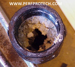
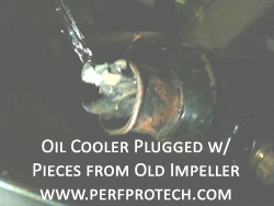
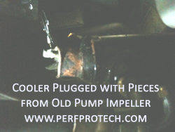
Raw-water sediment and debris may accumulate inside the heat exchanger. This debris may interfere with proper flow, causing overheating and increased wear of heat exchanger. The extent to which debris will build up depends on local water conditions and whether or not strainers or other devices are installed on the raw water inlet.
To clear debris from the heat exchanger, remove the end covers. Clear any accumulated debris. If a more thorough cleaning appears to be warranted, see “Debris blockage” and “Dirt buildup” in the troubleshooting guide. Upon reinstalling end covers, it may be necessary to use new gaskets. If frequent clean outs are necessary install strainers.
Corrosion inhibitor check
To obtain maximum benefits from FWC, the coolant should contain sufficient concentration of corrosion inhibitors. This inhibitor concentration should be checked every year by testing the solution for proper alkalinity level. Do this by using litmus paper. Paper will turn blue if coolant is alkaline and safe. If paper remains pink, coolant is acidic and should be replaced. Coolant in freshwater cooling system should be changed every 2 years.
General MARINE ENGINE winterizing
A freshwater cooling system is much easier to winterize than a raw-water cooling system since antifreeze solution already should be present on the freshwater side of the system. However, the raw-water part of the system must be properly winterized in order to prevent damage.
Before winterizing the cooling system, make sure that the rest of the engine has been properly winterized. Carefully study the engine manufacturer’s instructions and make sure that all the procedures that require running the engine have been performed. We assume that the engine, as part of the general winterizing, has been operated with a garden hose as raw-water supply.
Make sure that the raw-water side of the cooling system has received a thorough flushing before starting to winterize cooling system.
Freshwater sideCheck freshwater part of system to make sure that it contains antifreeze solution of sufficient concentration to handle the lowest temperatures expected in your area. Use a standard automotive type antifreeze tester. As to necessary strength, check information printed on antifreeze container or the chart in the flush and fill directions.
In addition, check the corrosion inhibitor concentration as outlined in general maintenance. For best protection, change antifreeze at least every other year or whenever the test indicates insufficient corrosion inhibitor concentration.
Raw-water side
Drain and clean raw-water side
Remove drain plug and zinc anodes from heat exchanger to drain raw-water. Remove demountable end covers and thoroughly remove any debris including zinc anode particles (if system has anode) that may have accumulated. Unless this debris is removed, it may not be possible to fully drain all the small internal tubes. It only takes trapped water in one tube to crack the tube and create a leaking heat exchanger.
Freeze damage is not covered under warranty, so make sure that a thorough job is done.
Be especially careful with horizontally mounted heat exchangers since capillary action tends to hold water in tubes. If compressed air is available, blow out any water trapped this way.
Reinstall drain plug, zinc anodes, and end covers. Upon reinstalling end covers, it may be necessary to use new gaskets.
Drain raw-water pump
Remove end cover from pump to let it drain. For best results, remove rubber impeller from pump. Spray it with silicone oil and store it separately to be used as a spare next season. Install fresh impeller every new season in order to make sure that raw-water pump functions properly. If convenient remove the entire pump from the engine and store it in a non-freezing area. For stern drive engine(s) with pump in stern drive, follow manufacturers instructions.
Drain engine on raw-water side
Following engine manufacturers instructions, drain all additional parts on raw-water system such as strainers, hoses, oil coolers, and exhaust system components.
Fill raw-water system with antifreeze
Draining all the raw-water from the system will protect the raw-water side from freeze damage. However, in order to protect the system from corrosion during storage fill the entire raw-water side with antifreeze that contains corrosion inhibitors. It also adds additional freeze protection in case the draining of the raw-water side was less than perfect.
Without running the engine, fill the raw-water side through a hose attached to the lowest part of the system. Leave drain plugs out but have them ready. Reinstall the plugs as the antifreeze reaches the different components and levels. By letting the antifreeze spill out before you reinstall the plug, you know the antifreeze reached everything without creating air pockets.
Check for leaks
Check to make sure there are no leaks on freshwater or raw-water side.
Remove end cover from pump to let it drain. For best results, remove rubber impeller from pump. Spray it with silicone oil and store it separately to be used as a spare next season. Install fresh impeller every new season in order to make sure that raw-water pump functions properly. If convenient remove the entire pump from the engine and store it in a non-freezing area. For stern drive engine(s) with pump in stern drive, follow manufacturers instructions.Drain engine on raw-water side Following engine manufacturers instructions, drain all additional parts on raw-water system such as strainers, hoses, oil coolers, and exhaust system components.
Remove end cover from pump to let it drain. For best results, remove rubber impeller from pump. Spray it with silicone oil and store it separately to be used as a spare next season. Install fresh impeller every new season in order to make sure that raw-water pump functions properly. If convenient remove the entire pump from the engine and store it in a non-freezing area. For stern drive engine(s) with pump in stern drive, follow manufacturers instructions.Following engine manufacturers instructions, drain all additional parts on raw-water system such as strainers, hoses, oil coolers, and exhaust system components. Fill raw-water system with antifreeze Draining all the raw-water from the system will protect the raw-water side from freeze damage. However, in order to protect the system from corrosion during storage fill the entire raw-water side with antifreeze that contains corrosion inhibitors. It also adds additional freeze protection in case the draining of the raw-water side was less than perfect. Check to make sure there are no leaks on freshwater or raw-water side.
Remove end cover from pump to let it drain. For best results, remove rubber impeller from pump. Spray it with silicone oil and store it separately to be used as a spare next season. Install fresh impeller every new season in order to make sure that raw-water pump functions properly. If convenient remove the entire pump from the engine and store it in a non-freezing area. For stern drive engine(s) with pump in stern drive, follow manufacturers instructions.Following engine manufacturers instructions, drain all additional parts on raw-water system such as strainers, hoses, oil coolers, and exhaust system components. Fill raw-water system with antifreeze Draining all the raw-water from the system will protect the raw-water side from freeze damage. However, in order to protect the system from corrosion during storage fill the entire raw-water side with antifreeze that contains corrosion inhibitors. It also adds additional freeze protection in case the draining of the raw-water side was less than perfect. Check to make sure there are no leaks on freshwater or raw-water side.
![]()
The Benefits of Fresh Water Marine Cooling Systems
Wednesday, February 15th, 2012Closed Cooling System – Tip’s
Wednesday, February 15th, 2012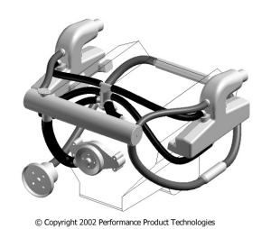
**WARNING – Make certain that the fresh water cooling system is not hot before removing the pressure cap. These systems normally operate with hot fluid under pressure. Injuries can result in carelessly removing the cap of a hot system**
FRESH WATER COOLING SYSTEMS – GENERAL TROUBLE SHOOTING
Temperature Problems
1. Before spending too much time chasing a temperature related problem, make certain the gauge is functioning properly by checking the gauge against a known good thermometer. Many inboard & I/O marine temperature sending units are the same basic devices produced for automotive applications. Since automotive engines normally operate at temperatures higher than marine engines, these devices can sometimes provide inaccurate readings. Bad gauges are one of the most common causes of problems. In our opinion no boater should be without an IR-Thermometer on board the boat at all times. You can shoot the temperature of the thermostat housing which should tell you whether the temperature that the gauge on the dash is reading is accurate or not.

2. Normal marine fresh water cooling systems allow the engine to operate at temperatures moderately above 160 degrees F. However, as the heat exchanger accumulates time the system may begin to operate in the range of 170 degrees F. NOTE – In most marine cooling systems a normally functioning system should never allow the engine to operate at temperatures in excess of 180 degrees F.
Thermostats
1. Marine engines utilize special thermostats specifically design to function in fresh water cooling systems. Although many people replace their marine thermostat with automotive replacements, in many cases they are subjecting their engine to conditions which will cause long term damage. In many cases this damage will not show up for a period of time, and do so in ways that appear unrelated to the cooling system.
2. Overcooling – Since the fresh water cooling system generally utilizes a heat exchanger designed for a particular application, the heat exchanger has been designed with a certain amount of capacity. This includes excess capacity to account for normal system degradation. Therefore, it is generally simple to identify overcooling related problems. These types of problems will almost always be thermostat related, usually an improper thermostat being used or something lodged in the thermostat and not allowing it to close properly.
3. Overheating – These types of problems can be more difficult to identify but in many cases related to a malfunctioning thermostat. Verify that the thermostat functions properly by inserting the thermostat into a pot of boiling water. Most thermostats will have the opening temperature stamped somewhere on the part, and should reach full stroke at approximately 20 degrees above the opening temperature. Thermostats are not repairable and should be replaced with the manufacturers specified part as these are system specific components.
Raw Water Pumps
1. Most fresh water cooling systems are designed with raw water pumps that provide approximately 30 – 35 gallons per minute (gpm) of water flow. Therefore, for a full fresh water cooling system (including the engine heat load as well as the exhaust system) the general temperature rise for the raw water will be approximately 50 degrees F. This means that if you were operating in 80 degree F water conditions, the water temperature exiting the heat exchanger and entering the exhaust risers should be in the range of 130 degrees F. The normal temperature tolerable to the touch is 140 degrees F. Therefore, if the proper amount of raw water is being delivered, the exhaust risers should feel hot to the touch, but tolerable.
2. Most sea water pumps used today utilize a flexible rubber impeller. While these types of impellers do a very good job at producing flow while tolerating a certain amount of debris, they are extremely susceptible to heat related dry run failures. While the Mercruiser style composite bodied water pump was very good at resisting corrosion, it lacked much in dry run capacity. This is due to the fact that composite materials do not dissipate heat nearly as well as metallic materials. To be on the safe side, an impeller should be changed at least every other season if not every season.
Step #3: Replace the Sea Water Pump Impeller (Watch “How To” Video)
Heat Exchangers
1. For most marine applications the tube and shell type of heat exchanger is used. However, larger commercial application will sometimes use a plate heat exchanger, but these are generally more expensive and very difficult to service.
2. In a tube & shell heat exchanger the raw water passes through the inside of the tubes, while the ethylene glycol passes on the outside of the tubes. Most generally the raw water side of the unit will allow for several water passes as increasing water velocities also increases heat transfer efficiencies. The glycol portion sometimes referred to as the shell side, generally allows for a single pass but has baffles to force the coolant flow upwards and downwards in an effort to also increase heat transfer.
3. One of the difficulties facing the marine cooling system, or any cooling system for that matter is in separating the air from the coolant. Air is a very poor conductor of temperature and therefore will force a cooling system to overheat almost immediately if a significant amount is contained within the fluid. Most original equipment heat exchangers now utilize a separation chamber to allow for the air to be separated from the fluid and then purged to the overflow bottle. Some marine engine manufacturers, and most automotive manufacturers now utilize a pressurized system which separates the air from the fluid and retains it in a structural designed reservoir. The main advantage of this design is the ability to service the system and allow for the highest level of system efficiency since it will constantly separate air from the fluid, not just when the engine is shut down and cooled (thermal-cycled).

Troubleshooting for Fresh Water Marine Cooling System
Wednesday, February 15th, 2012Shop the PPT Online Store to Buy Mercruiser Closed Cooling Systems….Read More
|
|
|
| Quick Launch Links | |||||
| Trouble Shooting Table | Leakage Problems | Temperature Problems | Overcooling | Overheating | Heat Exchanger Defects |
Temperature problems
Normal temperatures
Most marine FWC thermostats open at 160°F and will be fully open at approximately 180°F. A new clean system under moderate load should operate at the lower end of this range and a dirty system under full load might operate in the upper range. Any temperature that reads outside of this range is abnormal and should be investigated.
Temperature gauge problems
Before trying to diagnose a temperature problem, check the temperature gauge. Temperature gauges, especially electric, are often inaccurate and have temperature scales that are difficult to interpret. Before investigating a suspected temperature problem, check your temperature gauge against a thermometer of known accuracy.
Over-cooling
Though the most common problem is overheating, the opposite may also happen and will create long-term problems. Any good Fresh Water Cooling System should have excess cooling capacity. This compensates for the inevitable decrease in cooling capacity that results from the normal buildup of dirt on the heat transfer surfaces. In order to make sure that such a system, when new and clean, does not over-cool, a thermostat is used to control the flow of coolant to the heat exchanger. Over-cooling can only result from the thermostat not functioning properly.
Thermostat NOT functioning properly.
Check to make sure that the thermostat is of the right type. Do not assume that just because it fits it will function properly. There is a lot more to thermostat design than most people realize.
*DO NOT EXPERIMENT WITH UNAPPROVED THERMOSTATS*
Check to make sure that the thermostat is properly installed.
If the right type and correctly installed, make sure thermostat functions properly by immersing it in hot water of known temperature. The easiest way is to use a pot of water on a stove with an accurate thermometer. Hold thermostat by the flange with a pair of pliers. Do not let either thermostat or thermometer rest against bottom of pan. Thermostat should open at temperature marked on it and be fully open approximately 20°F higher. It should close again when immersed in colder water. Malfunctioning thermostats cannot be repaired, they must be replaced: make sure you get the right type.
Overheating
Overheating problems can be categorized into three basic problems, which either alone or in combination with one another will create overheating. They are lack of raw-water flow, lack of freshwater flow, and heat exchanger defects.
Lack of raw-water flow
Lack of raw-water flow will show up as an excessive increase of the raw-water temperature as the raw-water passes through the cooling system. Normal temperature increase varies between different engine models but is usually in the range of 40-60°F. In other words, if incoming raw-water temperature is 70°F, the outgoing water passing through the exhaust elbows will be in the range of 110-130°F. This will create surface temperatures on the elbow that will be warm but not excessively hot. Therefore, the easiest way to identify a raw-water problem is to check whether the engine overheating is combined with excessive temperatures on the outlet side of the raw-water system. If the raw-water side is to blame, there could be three basic reasons.
Restrictions on the inlet side of the raw-water pump
Of the pump could be design problems such as undersized plumbing. In addition, it could be maintenance problems such as debris buildup in seacocks, strainers or other components located on the suction side of the raw-water system. Check and clean.
Raw-water pump problems
The most common pump in use today is the rubber impeller pump. The impeller in this pump must never be run dry or it will be ruined. Eventually this impeller will also lose some of its flexibility due to old age and lose capacity.
In order to be on the safe side, we recommend that you replace the impeller annually especially if it is located in the sterndrive and difficult to service during the season. Keep the old impeller as a spare. If the impeller is damaged with blades missing, make sure that you find the missing blades. They could be stuck downstream from the pump interfering with proper flow. If raw-water pump is belt driven, make sure that belt has correct tension.
Restrictions on the outlet side of the raw-water pump
These restrictions are often in the form of raw-water debris accumulating on the inlet side of oil coolers and heat exchangers. Always check the units closest to the pump first and work yourself downstream.
Exhaust elbow clog
Over a few years, a problem with rust buildup in the exhaust elbows may develop. Many exhaust elbows have several small holes in the area where the raw-water enters the exhaust pipe. These orifices are designed to ensure proper water distribution at this point. Unfortunately, because of their small diameter they tend to be clogged with the rust particles that a raw-water-cooled elbow gives off. Eventually, an exhaust elbow may be completely plugged up preventing raw-water from entering the exhaust pipe and thereby creating a fire hazard.
In an in-line engine with a single exhaust elbow, this complete blockage will automatically cause engine overheating before the exhaust overheats. This will signal a problem before a fire hazard develops.
In a V-type engine however, the situation is more dangerous since one elbow could become plugged and the other one not. In this case, sufficient raw-water may be able to exit through the open elbow to keep enough raw-water flowing through the engine heat exchanger. The engine may not overheat but the plugged elbow, exhaust manifold, and exhaust pipe could burn and be destroyed.
We recommend that you periodically during the season feel the exhaust elbows to make sure that they stay at a normal and even temperature. Clean or replace these elbows before they cause further damage. Periodic flushing of the engine with freshwater will help minimize these problems.
Lack of freshwater flow
Lack of freshwater flow will show up as an increase in the temperature difference between in and outlet of heat exchanger. Most modern engine(s) have a flow rate at a level where the temperature difference between in and out on a block only system, will be in the range of 10-20°F. If manifolds are included in freshwater system, add another 10-20°F. Most people find 140°F to be the approximate max temperature that they can leave their hand on without discomfort. Since freshwater temperatures normally are above 160°F, it is not practical to check this difference without special equipment. If the engine is cool enough to be touched, it is probably running too cold. If lack of freshwater flow is the problem, these are the basic causes of it.
Restrictions on suction side of jacket water pump
Besides design problems such as an undersized heat exchanger outlet connection and/or hose, the only thing that can go wrong would be a hose being sucked closed. That is why hoses on the suction side, unless they are very short, should be either wire reinforced or have a loose spring inside to prevent collapsing.
Jacket water pump problems
Some older designs may have a rubber impeller pump or even gear pumps. If so, the rules relating to raw-water pumps apply.
Since rubber swells at increasing temperatures, it may be a good idea to give the pump impeller more space by using a thicker gasket under the pump cover. In addition, it is a good idea to use a full 50/50 antifreeze solution since the antifreeze will help lubricate the pump.
The vast majority of modern marine engine(s) use the standard automotive centrifugal jacket water pump. If these pumps have been operated in a raw-water system, they may have corrosion damage and may need to be repaired or replaced. Otherwise, this pump is very trouble free. The only service necessary should be to make sure that it operates at proper speed, by checking that the drive belt is not slipping. In the long run, it may develop a leak or bad bearing, just like in a car, but will continue pumping and is seldom causing overheat problems.
Be aware that if the engine is opposite rotation from the automotive standard, the pump may have a somewhat lower flow rate, which may result in slightly higher operating temperatures.
Restrictions on pressure side of jacket water pump
In this category belongs: engine internal blockage, malfunctioning thermostats, and restrictions in the inlet side of the heat exchanger.
Engine internal blockage
It is very unusual that a freshwater-cooled engine would have this problem. If an engine that has been operated on raw-water is converted to FWC, it is possible that old rust and scale deposits will create restrictions. That is why it is important to try to remove as much of this rust and scale as possible, as part of the installation process. Some of the debris may not come loose until normal engine operating conditions with higher jacket water flow, heat, and vibration. It is unusual that this debris will create blockage within the engine. More likely, it will be flushed along and are struck in the heat exchanger.
Malfunctioning thermostats
The thermostat has a very important function in any cooling system. If stuck in an open position it will cause overcooling and if stuck closed, overheating. Its function is more complicated than most people realize. Even a fully open thermostat creates a restriction at the outlet of the engine. This restriction is designed into the system in order to build up pressure in the engine block to help suppress localized internal boiling. Removing a thermostat that is not opening may work as a temporary solution to an overheating problem. If so, it should strictly be used in an emergency and the engine should only be operated under minimal load. As to how a thermostat should be tested, see previous discussion about overcooling problems.
Restrictions in the inlet side of the heat exchanger
Any debris that may work itself loose in the engine block may be flushed along and get stuck at the inlet of the heat exchanger a form a restriction. If this happens the heat exchanger should be back-flushed, that is flushed with water going in the opposite direction from normal. Depending on heat exchanger design and location this may or may not be possible to do with the heat exchanger installed. The best way is to do it with the heat exchanger removed so that it can be turned with the inlet down and let both water flow and the force of gravity help remove debris.
Heat exchanger defects
Since heat exchangers contain no moving parts there is very little that can go wrong with them except that they can be plugged with debris and that they will become dirty. They can also develop internal and external leaks. Leaks will be covered in the next category of troubleshooting. There is also the possibility that a heat exchanger is insufficient in capacity and/or incorrectly manufactured. Those problems, however, will show up immediately upon start-up and the manufacturer should be contacted. In this discussion, we are concerned with the problems that could develop during normal usage.
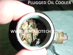
Debris blockage
The most common problem is where enough debris accumulates in the inlet chamber of the heat exchanger, to prevent the raw-water from passing through the tubes and pick up the heat. Since all good heat exchangers should have an existing de-mountable end cover at the inlet and it should be a simple operation to remove this debris. If the problem persists due to local water conditions install a good capacity raw-water strainer in the raw-water inlet hose. Even better is a good hull mounted strainer that will prevent debris from entering the system in the first place. Obviously there is a different solution depending on whether the raw-water intake is through a seacock or a sterndrive.
Dirt build-up
The more long-term problem with heat exchangers is the gradual slow build-up of dirt on both the inside and outside of the small tubes that form the heat transfer area. This will gradually build up as a layer of insulation and is compensated for in every good heat exchanger design by so called “fouling factor”. This simply means the heat exchanger has excess capacity when new and clean so it still performs acceptably when old and dirty. However, “fouling factor” can only go so far and eventually a thorough cleaning of the heat exchanger may be necessary.
Proper cleaning is a two-step operation. First, clean the unit with a strong alkaline solution to remove organic dirt such as oil. Second, clean the unit in an acid solution to remove scale. The most drastic solution is to remove the heat exchanger and take it to a radiator shop for a complete cleaning. Make sure that the radiator shop has experience with marine heat exchangers.
If a less thorough cleaning is desirable, the heat exchanger can be left in the system. The jacket waterside can be cleaned in the same way as an automobile cooling system using any of the better radiator cleaning solutions on the market. The small tubes on the raw-water side can be cleaned by using a small diameter long handle brush, similar to what is used for cleaning a rifle barrel. It is possible to acid clean the raw-water side of the heat exchanger without removing it from the boat, but it is messy and dangerous. The ports of the heat exchanger will have to be plugged and the unit filled with an inhibited muriatic acid. Since an operation like that necessitates special safety equipment and creates a disposal problem we do not recommend that you try it unless you really know what you are doing.
External & internal leaks
External leaks are the ones where the liquid leaks to the outside of the cooling system and can be seen or felt. Internal leaks are impossible to see or feel directly since they allow liquid to leak into internal area of the cooling system or the engine. Since they are more difficult to find and therefore may go on longer, they are often the most serious ones.
Raw-water leaks
External leaks
External leaks on the raw-water side seldom create major problems until they reach a high level. They should be fixed since a small leak easily could develop into a major one. Raw-water can do major damage if allowed to encounter other components, especially electric ones.
Besides the direct damage that a raw-water leakage can do, it may also be a warning signal for other problems. Leaks may start due to pressure build-up in the system resulting from raw-water blockage in either heat exchangers or exhaust system.
Internal leaks
The result of an internal leak will depend on the pressure existing on either side of the leak. On a FWC equipped engine, raw-water can still enter internally into the engine or transmission through raw-water cooled oil coolers. Raw-water can also get into the engine jacket through the main heat exchanger, as well as, enter the engine cylinders through leaky raw-water-cooled exhaust manifolds and exhaust elbows. Any of the above fluids may also go the other way and enter the raw-water system.
Which way the leak will go will depend on which fluid is under the most pressure and usually will depend on whether or not the engine is running. The leak might go one way when the engine is not running and the other way when it starts up.
Either way these leaks are very serious and must be caught early or serious engine damage may result. Check engine and transmission fluid levels frequently and be alert to any abnormal changes in levels as well as condition of fluid.
Freshwater leaks
External leaks
External leaks o n the freshwater side may eventually create enough loss of coolant to create an overheating situation. Once the safety margin in the expansion tank is used up, air will enter the closed system. Since a mixture of air and coolant is insufficient as a heat carrier overheating will result.
Some leaks may be difficult to find unless system is under pressure. This pressure is created by normal engine temperature. Since trouble shooting for safety reasons should be done on a cold engine, the system may have to be artificially pressurized to show a leak. A solution to this problem is a pressurizing pump for trouble shooting automobile cooling systems available from most auto supply stores. This type of pump usually includes a pressure gauge that will confirm the presence of a leak.
Internal leaks
Internal leaks o n the freshwater side can be internal to the heat exchanger. The freshwater will leak out into the raw-water side and escape. To check for this type of leakage, remove end covers from heat exchanger and drain raw-water. Most antifreeze solutions have a color to them and are easy to see if they leak out into the raw-water part of the heat exchanger. If operating on plain water, it may be desirable to dye water with food coloring to be able to see. Pressurizing the freshwater side will help locate the leak.
Engine leaks
A more serious form of internal leak would be one within the engine where the coolant, leaks into the cylinders through a leaky head gasket. This type of leak will usually show up when combustion gases are pushed into the jacket water when the engine is running and under load . It will show up as a steady stream of bubbles being pushed through the clear tubing leading from the heat exchanger to the expansion tank. Do not confuse with normal start up de-aeration. A device called “bloc check” is available from the auto supply stores, which will analyze the gases being pushed out from the cooling system and show whether they are air or combustion gases. A leaky head gasket problem is very serious and should be attended to immediately by a professional mechanic. It may result in coolant contaminating the oil. This is why we recommend running an engine initially on plain water to confirm that no leaks exist. At worst, the leaking coolant could accumulate in a cylinder and upon start-up bend a connecting rod due to hydraulic lock.
Fixing leaks
Permanent repairs
The best way is to create a permanent solution by bringing the leaking components into the proper condition. If major components such as the heat exchanger leaks, make sure they are repaired or replaced by competent professionals, preferably by referring them to manufacturers. Use only material suitable for marine use. Make sure that you get to the root of the problem so that you don’t put a “patch on a patch”. If a problem appears persistent or suspicious, make sure that you carry enough tools and spare parts aboard so that you have a chance to fix it again if the problem would reappear while under way.
Temporary field fixes
They should strictly be used to bring you back from a trip to proper repair facilities. Auto supply stores normally have hose repair kits that could come in handy. Also available are cooling system sealers. These products can be tried as temporary solutions to leaks on the freshwater side. Hardening putty of an epoxy type if also available and may prove useful. Always carry extra hose and hose clamps aboard for emergency repair.
The Basics of Marine Fresh Water Cooling Systems
Wednesday, February 15th, 2012
| Description | Capacity | Galley Heaters | Installation Time | Filling & Flushing |
| Start Up | Antifreeze Ratio | Warranty | Returns | Diagram |
| Freezing Point |
Heat exchanger
High-flow, shell and tube design allowing a higher cooling capacity than standard. All copper alloy construction made to the highest industry standards. Reinforced removable clean-out covers are installed on both ends of heat exchanger.
Cooling system capacity
Will maintain coolant temperatures in the 160-170 ° F range using 160 ° F thermostat included in kit. System has cooling capacity safety margin higher than industry standards.
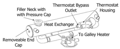
Galley water heating
Heaters such as galley water heaters and cabin heaters are easily supplied with hot water. Most of our kits utilize a 3/8” NPT fitting on top of the lower heat exchanger bracket to supply the heater inlet. When the 3/8” NPT fitting is supplied, instructions for the hook-up of the heater are supplied in the kit installation instructions.When no 3/8” NPT fitting is available, the heater inlet can be supplied by teeing off the heat exchanger bypass line. The outlet to the heater should be connected to a fitting on the engine-circulating pump (normally a ½” NPT thread).
Installation time
Average installation time is approximately 1-4 hours, assuming new engine and normal accessibility. Allow additional time for filling and testing. Installation skills are not beyond those of most do-it-yourself boat owners. Complete illustrated installation instructions are included in kit. Ordinary hand tools used, however a hose cutting tool, pipe thread and gasket sealant, and a mild thread locker is recommended.
General fill & start up
Double check installation
Before filling double-check entire installation. All fasteners, fittings, and hose clamps must be tight. Make sure engine drain plugs are in place.
Initial filling and flushing
An initial fill and flush is recommended, although not necessary for a brand new engine. This fill is to check the system for leaks and to help remove any sediment that remains in spite of the cold-water flush that was performed as part of the installation. For engines that have been previously cooled with raw-water, the flushing is critical. For more information, see the section on silicate dropout in the antifreeze section of these instructions.
The system should be filled with clean soft water. If local tap water is hard, we recommend distilled water, or drain water from air conditioners or dehumidifiers. Fill slowly through filler neck on top of the heat exchanger until completely full. Be careful not to damage the gasket surfaces of the filler neck with hose or tools.
Start-up dockside
Make sure that engine has normal raw-water supply. Start engine(s) and run at idle. Periodically during warm-up, check temperature of exhaust elbow(s) by touching them with your hand. The elbow(s) should rise in temperature equally.
If elbow(s) is too hot, stop immediately and investigate reason for insufficient raw-water supply. See troubleshooting instructions.
Upon start-up, water level will drop as trapped air from inside engine block is expelled through filler neck. Continue to fill to maintain water level until most of the air has escaped. This should only take a couple of minutes. Fill completely to top of filler neck and put pressure cap on.
Fill (plastic) expansion tank half full and continue running until system is fully warmed up to thermostat opening temperature (usually 160°F). Gunning the engine a few times during this warm-up period will increase jacket water flow rate and help expel air. As air bubbles disappear in clear tubing leading from the heat exchanger to expansion tank add enough water in expansion tank to fill it to its normal level (approximately 2/3 full).
Check system over to make sure there are no leaks.
Test run
If everything appears to function properly, take boat for a test run.
Gradually and in steps, increase power while observing temperature gauge. Temperature may increase slightly from those at idle level. When throttling very quickly from full power back to idle a temporary temperature increase may be observed.
If temperature is too hot (above 185°F), stop immediately and investigate reason for insufficient raw-water supply. See troubleshooting instructions.
If temperature on temperature gauge appears abnormal, make sure that the gauge is accurate before taking additional steps. Electric type temperature gauges are frequently inaccurate. See troubleshooting instructions.
Final flush and fill
If everything functions normally, return to dock, stop engine(s) and let cool down. After complete cool down, drain and flush system completely.
If engine is old , it may be desirable to keep the engine operating for some time with only clean distilled water. See the section on silicate dropout in the antifreeze section of these instructions. Periodically during the season, repeat the draining/flushing procedure before converting to correct antifreeze solution.
If engine is new, or the engine has been properly flushed , refill system with antifreeze and repeat start-up procedures. If clean soft water is not readily available, consider using a 50% premix antifreeze solution.
When system is hot, correct coolant level in expansion tank is approximately 2/3 full. Whatever the drop is, mark it on the expansion tank. If system when cool is lower than normal, it indicates a coolant leak. If level is higher, it may indicate that air instead of coolant sucked back from expansion tank. Either condition should be corrected. See troubleshooting instructions.
Antifreeze coolant
As a permanent coolant on the freshwater side, use an antifreeze solution of sufficient strength to handle the lowest temperature that could be expected during winter lay up. Use at least a 10% solution of anti-freeze. Do not exceed 50% antifreeze strength. MONITOR recommends the use of a 1/3 solution if possible. We recommend that you use distilled water especially if your local tap water is hard.
If the percentage of antifreeze is less than 1/3, add additional corrosion inhibitor.
Antifreeze solutions provide some corrosion protection for the engine. However, solutions less than 1/3 anti freeze do not have sufficient corrosion protection for maximum engine life. For that reason, if the percentage of antifreeze is less than 1/3, add additional corrosion inhibitor.
DO NOT USE PROPYLENE GLYCOL BASED ANTIFREEZE.
PPT/MONITOR recommends the use of an “Extended Life”, “Low/non Silicate” anti-freeze such as DEX-COOL ® .
To prevent “silicate dropout”, PPT/MONITOR recommends the use of any antifreeze that meets the General Motor’s Extended Life Coolant Specification (DEX-COOL®). These antifreezes are readily available at diesel engine supply stores.
When silicates present in antifreeze drop out, they build up and form a gel. This is called silicate dropout. A number of things can start this process: high silicate levels from incorrect antifreeze concentrations or improper use of coolant additives, impurities in very hard water, and severe engine temperature swings. “Boiler-scale” (calcium salts), especially present in used engines, present the largest threat of silicate dropout . It is therefore extremely important that used engines are thoroughly flushed. It is best to run the engine using only clean distilled water until much of the calcium salts have dissolved.
The main effects of the formation of this silicate gel are clogging of the heat exchanger, and engine overheating. Silicate gel buildup greatly reduces heat transfer to the coolant. When the gel coats the temperature sender, engine overheating can take place without notice. Silicate gel also carries abrasive particles to the water pump, where it wears away pump seals causing leakage and failure.
There are few effective methods for cleaning the gel from an already-clogged system. The heat exchanger must be removed and sent out for a thorough cleaning. The engine must be flushed with a caustic solution. The gel is not water soluble, so flushing with water alone will not work.
When using “Extended Life”, or “Low/non Silicate” anti-freezes, be careful NOT to mix with higher silicate antifreezes or hard water.
Use of too strong of an antifreeze solution can hinder heat transfer from the engine, and promote silicate dropout. Pure water conducts heat better than antifreeze and corrosion inhibitor; therefore, the addition of antifreeze or other chemicals reduces the water’s capacity to draw heat off the engine. A 1/3 solution is recommended so that no additional corrosion inhibitors need to be added.
Warranty
PPT/Monitor Products, Inc warranties the components in this kit against defects in material and workmanship for a period of two years from the date of original purchase.
All obligations and liabilities under this warranty are limited to repairing or replacing at monitor products option any components returned freight prepaid to our offices and found defective. No liability is assumed for indirect cost relating to labor charges or other indirect consequential damages.
The warranty does not cover units that have been used for commercial or racing applications, nor does it cover damage due to corrosion or freezing.
Money back guarantee
All PPT/Monitor products offer a full refund of purchase price for kits returned within 30 days of shipping date. Authorization to return kit must be obtained in advance. Kit must be returned in original box and be in unused and undamaged condition. If not, repair charges will be deducted from refund.
Shipping instructions
Any component returned to PPT/monitor products for whatever reason must be packed very well and is returned freight prepaid. Heat exchangers, due to their copper alloy construction, are especially easy to damage and must be carefully packed if shipping damage is to be avoided. Any shipping damage will be deducted from refund.