Posts Tagged ‘fresh water cooling’
1/2 versus Full Fresh Water Cooling Systems
Wednesday, February 15th, 2012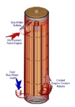   Questions: 1) What are the differences between Fresh Water Cooling Systems and Raw Water Cooling Systems 2) What is the Difference Between a Full & Half Closed Cooling System? Response: Half Systems vs. Full Systems:
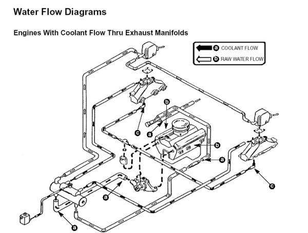
In all cases prior to installing the system, you will want to flush out your block with tap water to prevent any loose debris from lodging into the heat exchanger once it is installed. Another helpful hint with older products is to create a pocket using a piece of “Panty Hose”. Install this over the inlet of the heat exchanger (connection leading from the thermostat housing) before installing the coolant hose and hose clamp. Run the engine for about 30 minutes with straight tap water. This will act as a filter and collect the debris and scaling form the engine thereby preventing it from lodging in the heat exchanger which reduces it’s overall effectiveness. Cooling System Products Fresh Water Cooling FULL System Flow Diagram
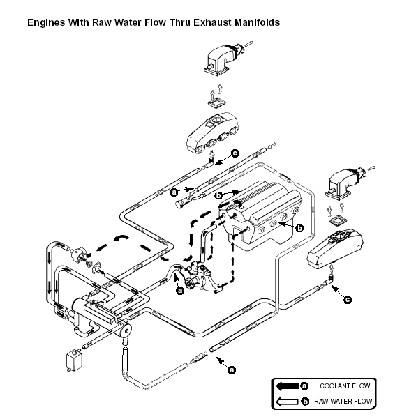
Fresh Water Cooling HALF System Flow Diagram Below
|

Marine Fresh Water Cooling System Maintenance Tips
Wednesday, February 15th, 2012
| Location & Service | When Starting Engine Each Day | After Use Each Day | Every 30 Days | After 1st 20 hours | Every 50 Hours | Every 100 Hours | Once/Year | Once/2 Years | Storage |
| Check for Leaks | X | ||||||||
| Maintain Coolant Level | X | ||||||||
| Flush Seawater Section of Cooler | X | ||||||||
| Check for Marine Growth or Debris at Water Pickup | X | ||||||||
| Fasteners – Check for Tightness | X | X | X | ||||||
| Hose Clamps – Check for Tightness | X | X | X | ||||||
| Drive Belts – Inspect | X | X | X | ||||||
| Check and/or Replace Anodes | X | X | |||||||
| Hoses – Check for Cracks and Wear | X | X | |||||||
| Pressure Cap – Clean, Inspect & Test | X | X | |||||||
| Seawater Pickup | X | ||||||||
| Remove Debris on Raw Water Side | X | ||||||||
| Check Corrosion Inhibitor Status of Coolant | X | ||||||||
| Replace Raw Water Pump Impeller | X | ||||||||
| Change Coolant | X | ||||||||
| Clean Closed Coolant Section | X | ||||||||
| Drain and Clean Raw Water Section | X |
WARNING : Never remove pressure cap from a hot system. Allow system to cool down. Turn pressure cap 1/4 turn to allow pressure to escape slowly. Then push down & turn pressure cap off completely.
Maintain coolant level
Before starting engine always, check coolant level in expansion tank. See fill & start up instructions. If coolant level is down, check for leaks in the system and repair. See trouble shooting instructions.
Check for marine growth
Check for marine growth or debris at water pickup. Clean, if necessary.
Make sure drive belts on the engine are tight so that the system pumps will function properly. Check their condition, and replace as required.
Check zinc anode (If Present)
Zinc anode should be checked every 50 hours of operation or at least annually. If zinc part of plug is corroded to a point or less than half its original size, replace it.
Clean and inspect pressure cap
The pressure cap is designed to hold a pressure of 16psi (110kPa) in the closed coolant system. This raises the boiling point of the coolant, raising its efficiency. Carefully remove the cap from the system. Wash the cap and the filler neck with clean water to remove any deposits or debris. Inspect the cap seals for cuts, cracks, or other signs of deterioration. Replace the cap if it is bad.
Remove debris on raw-water side
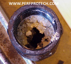
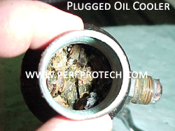
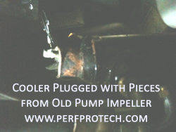
Raw-water sediment and debris may accumulate inside the heat exchanger. This debris may interfere with proper flow, causing overheating and increased wear of heat exchanger. The extent to which debris will build up depends on local water conditions and whether or not strainers or other devices are installed on the raw water inlet.
To clear debris from the heat exchanger, remove the end covers. Clear any accumulated debris. If a more thorough cleaning appears to be warranted, see “Debris blockage” and “Dirt buildup” in the troubleshooting guide. Upon reinstalling end covers, it may be necessary to use new gaskets. If frequent clean outs are necessary install strainers.
Corrosion inhibitor check
To obtain maximum benefits from FWC, the coolant should contain sufficient concentration of corrosion inhibitors. This inhibitor concentration should be checked every year by testing the solution for proper alkalinity level. Do this by using litmus paper. Paper will turn blue if coolant is alkaline and safe. If paper remains pink, coolant is acidic and should be replaced. Coolant in freshwater cooling system should be changed every 2 years.
General MARINE ENGINE winterizing
A freshwater cooling system is much easier to winterize than a raw-water cooling system since antifreeze solution already should be present on the freshwater side of the system. However, the raw-water part of the system must be properly winterized in order to prevent damage.
Before winterizing the cooling system, make sure that the rest of the engine has been properly winterized. Carefully study the engine manufacturer’s instructions and make sure that all the procedures that require running the engine have been performed. We assume that the engine, as part of the general winterizing, has been operated with a garden hose as raw-water supply.
Make sure that the raw-water side of the cooling system has received a thorough flushing before starting to winterize cooling system.
Freshwater sideCheck freshwater part of system to make sure that it contains antifreeze solution of sufficient concentration to handle the lowest temperatures expected in your area. Use a standard automotive type antifreeze tester. As to necessary strength, check information printed on antifreeze container or the chart in the flush and fill directions.
In addition, check the corrosion inhibitor concentration as outlined in general maintenance. For best protection, change antifreeze at least every other year or whenever the test indicates insufficient corrosion inhibitor concentration.
Raw-water side
Drain and clean raw-water side
Remove drain plug and zinc anodes from heat exchanger to drain raw-water. Remove demountable end covers and thoroughly remove any debris including zinc anode particles (if system has anode) that may have accumulated. Unless this debris is removed, it may not be possible to fully drain all the small internal tubes. It only takes trapped water in one tube to crack the tube and create a leaking heat exchanger.
Freeze damage is not covered under warranty, so make sure that a thorough job is done.
Be especially careful with horizontally mounted heat exchangers since capillary action tends to hold water in tubes. If compressed air is available, blow out any water trapped this way.
Reinstall drain plug, zinc anodes, and end covers. Upon reinstalling end covers, it may be necessary to use new gaskets.
Drain raw-water pump
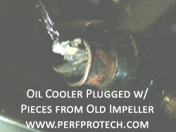
Remove end cover from pump to let it drain. For best results, remove rubber impeller from pump. Spray it with silicone oil and store it separately to be used as a spare next season. Install fresh impeller every new season in order to make sure that raw-water pump functions properly. If convenient remove the entire pump from the engine and store it in a non-freezing area. For stern drive engine(s) with pump in stern drive, follow manufacturers instructions.
Drain engine on raw-water side
Following engine manufacturers instructions, drain all additional parts on raw-water system such as strainers, hoses, oil coolers, and exhaust system components.
Fill raw-water system with antifreeze
Draining all the raw-water from the system will protect the raw-water side from freeze damage. However, in order to protect the system from corrosion during storage fill the entire raw-water side with antifreeze that contains corrosion inhibitors. It also adds additional freeze protection in case the draining of the raw-water side was less than perfect.
Without running the engine, fill the raw-water side through a hose attached to the lowest part of the system. Leave drain plugs out but have them ready. Reinstall the plugs as the antifreeze reaches the different components and levels. By letting the antifreeze spill out before you reinstall the plug, you know the antifreeze reached everything without creating air pockets.
Check for leaks
Check to make sure there are no leaks on freshwater or raw-water side.
Remove end cover from pump to let it drain. For best results, remove rubber impeller from pump. Spray it with silicone oil and store it separately to be used as a spare next season. Install fresh impeller every new season in order to make sure that raw-water pump functions properly. If convenient remove the entire pump from the engine and store it in a non-freezing area. For stern drive engine(s) with pump in stern drive, follow manufacturers instructions.Drain engine on raw-water side Following engine manufacturers instructions, drain all additional parts on raw-water system such as strainers, hoses, oil coolers, and exhaust system components.
Remove end cover from pump to let it drain. For best results, remove rubber impeller from pump. Spray it with silicone oil and store it separately to be used as a spare next season. Install fresh impeller every new season in order to make sure that raw-water pump functions properly. If convenient remove the entire pump from the engine and store it in a non-freezing area. For stern drive engine(s) with pump in stern drive, follow manufacturers instructions.Following engine manufacturers instructions, drain all additional parts on raw-water system such as strainers, hoses, oil coolers, and exhaust system components. Fill raw-water system with antifreeze Draining all the raw-water from the system will protect the raw-water side from freeze damage. However, in order to protect the system from corrosion during storage fill the entire raw-water side with antifreeze that contains corrosion inhibitors. It also adds additional freeze protection in case the draining of the raw-water side was less than perfect. Check to make sure there are no leaks on freshwater or raw-water side.
Remove end cover from pump to let it drain. For best results, remove rubber impeller from pump. Spray it with silicone oil and store it separately to be used as a spare next season. Install fresh impeller every new season in order to make sure that raw-water pump functions properly. If convenient remove the entire pump from the engine and store it in a non-freezing area. For stern drive engine(s) with pump in stern drive, follow manufacturers instructions.Following engine manufacturers instructions, drain all additional parts on raw-water system such as strainers, hoses, oil coolers, and exhaust system components. Fill raw-water system with antifreeze Draining all the raw-water from the system will protect the raw-water side from freeze damage. However, in order to protect the system from corrosion during storage fill the entire raw-water side with antifreeze that contains corrosion inhibitors. It also adds additional freeze protection in case the draining of the raw-water side was less than perfect. Check to make sure there are no leaks on freshwater or raw-water side.
![]()
Closed Cooling System – Tip’s
Wednesday, February 15th, 2012
**WARNING – Make certain that the fresh water cooling system is not hot before removing the pressure cap. These systems normally operate with hot fluid under pressure. Injuries can result in carelessly removing the cap of a hot system**
FRESH WATER COOLING SYSTEMS – GENERAL TROUBLE SHOOTING
Temperature Problems
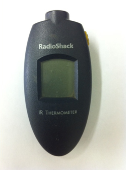
1. Before spending too much time chasing a temperature related problem, make certain the gauge is functioning properly by checking the gauge against a known good thermometer. Many inboard & I/O marine temperature sending units are the same basic devices produced for automotive applications. Since automotive engines normally operate at temperatures higher than marine engines, these devices can sometimes provide inaccurate readings. Bad gauges are one of the most common causes of problems. In our opinion no boater should be without an IR-Thermometer on board the boat at all times. You can shoot the temperature of the thermostat housing which should tell you whether the temperature that the gauge on the dash is reading is accurate or not.
2. Normal marine fresh water cooling systems allow the engine to operate at temperatures moderately above 160 degrees F. However, as the heat exchanger accumulates time the system may begin to operate in the range of 170 degrees F. NOTE – In most marine cooling systems a normally functioning system should never allow the engine to operate at temperatures in excess of 180 degrees F.
Thermostats
1. Marine engines utilize special thermostats specifically design to function in fresh water cooling systems. Although many people replace their marine thermostat with automotive replacements, in many cases they are subjecting their engine to conditions which will cause long term damage. In many cases this damage will not show up for a period of time, and do so in ways that appear unrelated to the cooling system.
2. Overcooling – Since the fresh water cooling system generally utilizes a heat exchanger designed for a particular application, the heat exchanger has been designed with a certain amount of capacity. This includes excess capacity to account for normal system degradation. Therefore, it is generally simple to identify overcooling related problems. These types of problems will almost always be thermostat related, usually an improper thermostat being used or something lodged in the thermostat and not allowing it to close properly.
3. Overheating – These types of problems can be more difficult to identify but in many cases related to a malfunctioning thermostat. Verify that the thermostat functions properly by inserting the thermostat into a pot of boiling water. Most thermostats will have the opening temperature stamped somewhere on the part, and should reach full stroke at approximately 20 degrees above the opening temperature. Thermostats are not repairable and should be replaced with the manufacturers specified part as these are system specific components.
Raw Water Pumps
1. Most fresh water cooling systems are designed with raw water pumps that provide approximately 30 – 35 gallons per minute (gpm) of water flow. Therefore, for a full fresh water cooling system (including the engine heat load as well as the exhaust system) the general temperature rise for the raw water will be approximately 50 degrees F. This means that if you were operating in 80 degree F water conditions, the water temperature exiting the heat exchanger and entering the exhaust risers should be in the range of 130 degrees F. The normal temperature tolerable to the touch is 140 degrees F. Therefore, if the proper amount of raw water is being delivered, the exhaust risers should feel hot to the touch, but tolerable.
2. Most sea water pumps used today utilize a flexible rubber impeller. While these types of impellers do a very good job at producing flow while tolerating a certain amount of debris, they are extremely susceptible to heat related dry run failures. While the Mercruiser style composite bodied water pump was very good at resisting corrosion, it lacked much in dry run capacity. This is due to the fact that composite materials do not dissipate heat nearly as well as metallic materials. To be on the safe side, an impeller should be changed at least every other season if not every season.
Step #3: Replace the Sea Water Pump Impeller (Watch “How To” Video)
Heat Exchangers
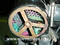
1. For most marine applications the tube and shell type of heat exchanger is used. However, larger commercial application will sometimes use a plate heat exchanger, but these are generally more expensive and very difficult to service.
2. In a tube & shell heat exchanger the raw water passes through the inside of the tubes, while the ethylene glycol passes on the outside of the tubes. Most generally the raw water side of the unit will allow for several water passes as increasing water velocities also increases heat transfer efficiencies. The glycol portion sometimes referred to as the shell side, generally allows for a single pass but has baffles to force the coolant flow upwards and downwards in an effort to also increase heat transfer.
3. One of the difficulties facing the marine cooling system, or any cooling system for that matter is in separating the air from the coolant. Air is a very poor conductor of temperature and therefore will force a cooling system to overheat almost immediately if a significant amount is contained within the fluid. Most original equipment heat exchangers now utilize a separation chamber to allow for the air to be separated from the fluid and then purged to the overflow bottle. Some marine engine manufacturers, and most automotive manufacturers now utilize a pressurized system which separates the air from the fluid and retains it in a structural designed reservoir. The main advantage of this design is the ability to service the system and allow for the highest level of system efficiency since it will constantly separate air from the fluid, not just when the engine is shut down and cooled (thermal-cycled).